Search This Blog

23 August 2010

The "Manhattan" Project ...

.. OK, maybe it's not quite on that scale, but it does involve
Manhattan-style kit construction.

My next project is a QRP wattmeter - created by the North Georgia
Radio Club and hence the kit's name: NoGaWaTT. The final product will
be housed in an Altoids tin. The ultimate in low-cost and compactness.

Once I finish the project I can complete final tube-up for my NorCal
40A.

... now to inventory!

08 August 2010

NorCal 40A Completed

Completed the kit on 7 August 2010. Had to fix a wiring problem on the
power supply cable that I made before I could power up and do VFO and
alignment work.

Completed alignment and tuning with just my ears (as QRP Bob advised).
Adjustments went smoothly.

For me, wiring the keyer to the rig was the most challenging part of
the kit. But I was successful wiring it up (with XYL help to hold some
components steady).

The KC1 keyer is really a great add-on that I highly recommend. With
it I was able to easily determine the lo and hi tuning ranges, once I
programmed in the VFO offset.

02 August 2010

Final Assembly Completed

Completed final assembly on July 31. The unit looks great! I really like the way the cover latches to the bottom of the case. Makes it a snap to get access to the PCB.

I still need to do testing and tuning. Since I only have an analog meter I'll mostly be tuning by ear.

Next, I need to assemble, install and set up the KC1 keyer unit. I thought I would test and tune the xcvr before installing the KC1 unit. Once the KC1 is up and running, I can check my frequency using its frequency counter capabilities.

No time to complete these work this week as we've got company, but I hope to begin work this weekend.

It will be great to get back on the air again.

31 July 2010

Toroid winding completed

Toroids on the right are transformers, each has two windings.

Large toroid on the bottom is for the VFO.

For me, having a good magnifier was key to good winding and properly
adjusting the spacing of windings, especially on the VFO toroid, which
has 60 turns of #28 enamel wire. I used a small plastic probe to make
spacing adjustments.

Next step: installation of toroids.

After that: installation of the unit's controls, connectors and panels.

Then: final assembly, tuning & testing.

18 July 2010

NorCal 40A kit progress

Fixed and adjustable capacitors installed.


Electrolytics, ICs and final amp installed.

Soldering is underway

Fixed resistors installed.

17 July 2010

Next project: NorCal 40A QRP xcvr


I'm ready to start my next QRP kit, the NorCal 40A 40m transceiver from Wilderness Radio.

Received the kit a few days ago and did the parts inventory. One resistor was missing, Bob's sending that. 

Here is a shot of the front and rear plates, the enclosure, PCB and bag o' parts.

Here are the parts ready for inventory.

Read the instruction manual, which is well-laid out and am really looking forward to getting started. I bought the KC1 keyer option as well.

27 June 2010

Field Day 2010 - Day 2 - Moscow, ID

My day started at 0400 PST on Sunday. I promised to work 0400 through station close and site break-down and clean-up with the Palouse Hills Amateur Radio Club.

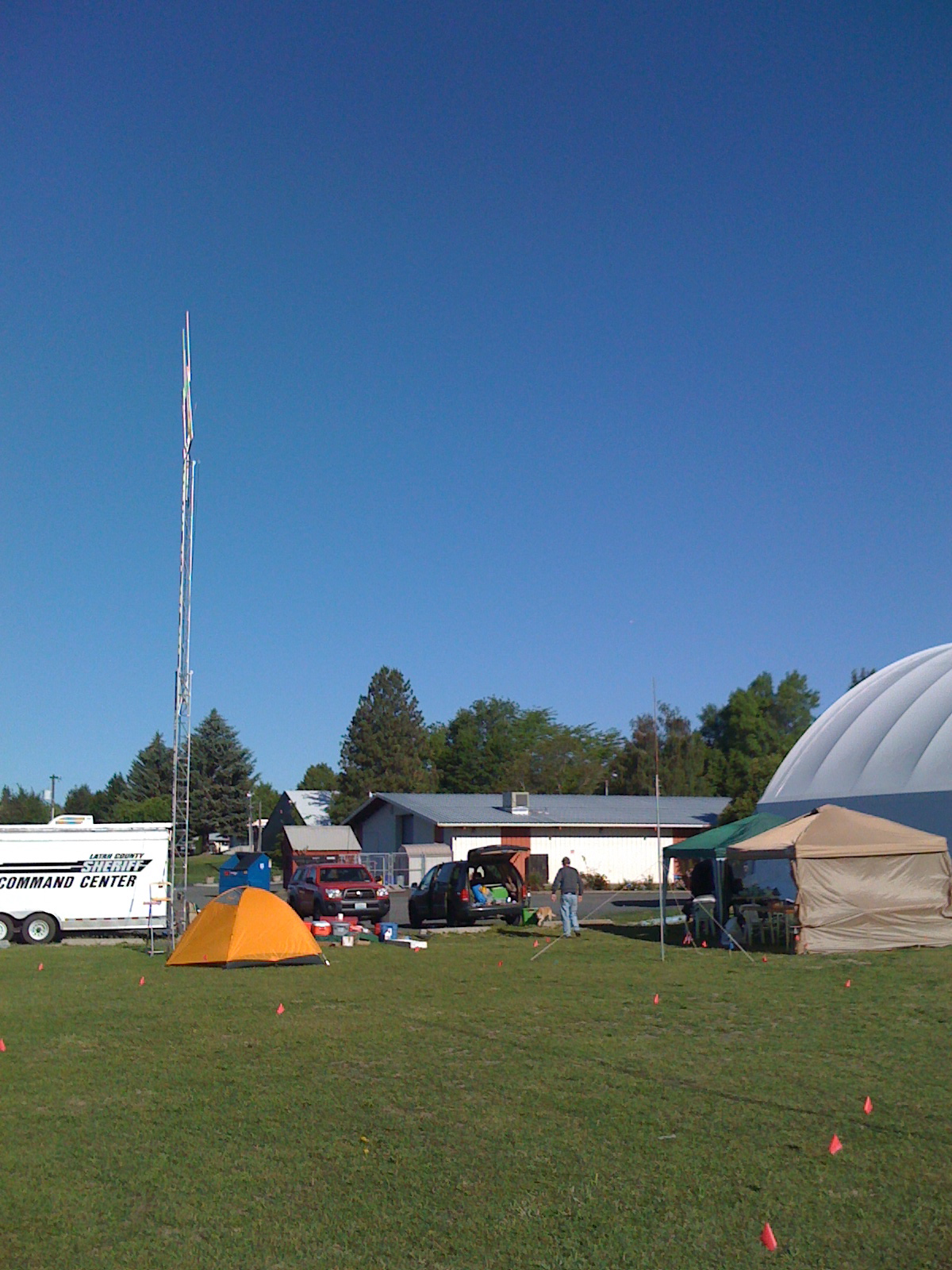
We were very fortunate to get the use of the county sheriff's emergency services trailer, which had some amateur radio gear already installed in it.

As it turns out, this particular emergency trailer (see photo below) had never been used until this Field day!

In a way it was fortunate as we uncovered several wiring and grounding issues that we addressed.

This worked out to be a great operating station and was able to accommodate several two-man operating positions throughout Field Day.

In addition, the trailer came with a nice crank-up tower which we put to good use to support some of our antennas. Nice.

One thing is for sure, we are now ready for true emergency operations since we now have first-hand experience with this unit. Next time (or I guess I should say the FIRST time) there is an emergency we'll be prepared should our assistance be needed to support emergency operations.

This next photo is a look at the tents that were set up for those
hardy souls who stayed overnight at our site. As it turned out, 80 meters really heated up and, at one point the guys cranked out over 100 QSOs in a hour! FB!


The only downside was sleeping on the ground, ah well, all for a good cause, right?

Next day W7NGI made cooked up some amazing pancakes and bacon to get things off to a solid start. Thanks, Ken! And he did it all on a classic Coleman propane camp cookstove.

Someone also brought in some ripe cherries (no doubt from Washington) which made a nice finish to breakfast.

...still not sure what that huge jar of pickles was all about, however...


Here's a shot of the combination breakfast and break tent set-up that was set up.


That's KI6DER, PHARC President, taking a break between sessions. BTW, if you ever need coax, he's your man.


Next, we've got a look inside the "shack:


That's KK7VO notching another contact in the early morning hours. I believe her dog Daisy (just out of view in this shot) was logging for her.  : - )


In the next shot, we've got Joe and Ken burning up the band on 40 meter phone. Ken's got logging duty while Joe's in the hot seat.

We worked many states from Alaska and Hawaii to Texas, Ohio, Vermont and Massachusetts and more.

We were able to work phone, PSK-31 and, after a fashion and thanks to KE6DWM, we were able to notch a few CW contacts as well, though not how I had anticipated. He was able to get us set up to run CW through his PSK interface to a Yaesu rig. Worked great. Couldn't use my key since the Yaesu has a mini jack and I had a 1/4 inch jack on my key.


The next photo shows one of the other operating positions we had set up

We also had a GOTA position set up, which was great since we had folks from as far away as Alaska (well kind of) stop by to visit.

In addition KE6DWM's XYL took and passed her Technician license during Field Day. Congratulations!!

Do we get extra points for that?  : -)


On top of that, she stuck around and made a bunch of contacts at the GOTA position.

Can her General class be far behind?

In this next photo we've got a shot of one of the "towers" we erected for our antennas. KK7VO had a 80-10m antenna attached with a nice loading coil near the center.

Although this shot only appears to show a single guy wire, there were two others that kept this pole in place.

It did a good job for us supporting, I believe, 3-4 antennas.

We wrapped things up at noon PST having racked up more overall points than our 2009 Field Day performance, not to mention all visitors we had.

All in all it was, for me, a great Field Day experience.

I'm really hoping that for Field Day 2011, I'm ready with a full, self-contained QRP CW operating position, complete with antenna.

I was the only one in PHARC able to copy code at this year's field day, so my QSOs got us a few extra points.


That's all for now.


I'll say 73 and look to see you all at Field Day 2011!


N7RCS

Field Day 2010 - Day 1 - Viola, ID

We had a fabulous weekend for Field Day 2010. Temperatures in North Idaho were in 70-80F with bright blue, clear skies and nary a raindrop in sight.  Woohoo!

Since I belong to 2 clubs in the Moscow-Pullman area I decided to participate with both clubs this Field Day. So on Saturday I joined my fellow hams in the Schweitzer Engineering Laboratories radio club (K7SEL).

We set up shop at N7CE in Viola, ID. Great location with lots of room to spread out, set up an antenna farm, rigs and other assorted Field Day gear. I arrived at about 0830 PST to get things started.

Here are Joseph and Ron getting a station and logging terminal set up set up in N7CE's "shack":

Feed lines run in through the wood insert in the window on the left. Battery power was on the floor, right below the laptop.

We operated phone, CW, and PSK-31 on Saturday and did a credible job, once some minor battery charging issues were resolved.

Got the chance to help set up antennas, rigs, feedlines and more. Really enjoyed it.

Here are a few more photos of set up and operating at N7CE:


Here is one operating position just about ready to go. Just had to run feed lines in from outside.

As for antennas, we had quite a range.

Below you'll see a nifty telescoping fibreglass pole we made into a 40 meter vertical. Light winds made it a cinch to set up and guy and it did a credible job for us, though not quite as good as the ladder line-fed dipole that was rigged up.

Here's the fibreglass vertical, ready to go, complete with pink safety strips to avoid "clotheslining" problems. Note the amazing view out beyond.

We would alternate between phone and CW when we rotated operators and loggers. 

We had one visitor to the station, see below, so we had an opportunity to show a non-ham what ham radio is all about and how the Field Day worked.

In the next photo, N7CE takes time to explain what all the fun is about to our visitor, Prasad. 


At about 1700 PST I had to head home at attend to things on the homefront.

Just before I left we took some time to get the 6 meter antenna up for the night crew. 

The next photo shows the 6-meter antenna before we got her raised up. 


Had some great chow, thanks to N7CE and his friend.

This was my first real Field Day experience since I began in ham radio back in the 1960s. I had been to a couple of Field Days but had never actually participated like I did here.  What a blast!

Then I headed home to Moscow to get ready for my 0400 PST wake-up call and rendezvous with fellow Palouse Hills Amateur Radio Club members at the Latah County Fair Grounds just east of beautiful Moscow, ID.

Luckily for me, the fair grounds are in walking distance from my QTH.


For details of my Sunday Field Day adventures read the next post. 

73!

N7RCS over and out.

22 June 2010

My first ham radio gear

Got to thinking about how I got started in ham radio and remembered the gear my Dad, somehow, obtained for me. Thinking back on it now, the gear he got me was really amazing! I'm pretty sure he got the transmitter, a crystal-controlled Heathkit DX-40 CW rig, at the local Lafayette radio store. The thing could put out 60w or so.

I think I had two JAN crystals, one for 40m and one for 15m! The rig had a hole on the right side where the crystals were inserted. I remember how great it was when I got two more crystals. Now I could actually switch frequencies on one band!

Those were the days... Anyway, I went over to RigPix and they had a photo of the Healthkit DX-40 in all its gray glory! Although I don't recall that my rig had an indicator light like this one does, this rig was built like a tank.


My antenna was a long wire that ran out the window frame and across the back yard to this old, unused phone pole that was probably on our neighbor's property. Any, as I recall it did a pretty credible job for me and was practically invisible to our neighbors because it was so small.

On the receiver side, my Dad, somehow, got hold of a Hallicrafters SX-130 shortwave receiver, a triple conversion superhet with some pretty slick filtering capabilities (at least for a 13 year old kid new to ham radio)! I actually still have it, although the plastic slide switch for selecting AM/SSB has cracked and no longer works. Tuning was a bit of a chore since you had to set one dial to calibrate the tuner for a specific band. The other dial handled fine tuning. Very simple set up.

Plus, this baby has a full complement of tubes and everything. Weighs a ton too. Nice. Here's an excellent picture from RigPix


I wish I knew how my Dad got this radio. Probably one of his IBM ham buddies. 

Thanks Dad for the unforgettable memories and getting me started in this great hobby!

19 June 2010

Stealth antenna and feedline

Where's the antenna? That's the point. You can't see it!
The design is a modified version of KR1ST's stealth HF coat
hangar antenna. Running QRP with an ICOM IC-706MKII
I've worked stations in Hawaii, New York, Texas and Chicago
from my humble QTH in Moscow, ID in the shadow of mighty
mile-high Moscow Mountain.

Even standing in front of the house on the sidewalk it's
virtually invisible. The 100 foot dipole is there, however, running
just beneath the second floor gutter.

As for the feedline, if you look very carefully you can see
the spacers on the open wire feedline. They appear as short
horizontal lines against the side of the dark green trim to the
left of the long window on the house.

The 100-foot dipole antenna and feedline
are actually two continuous lengths of #14
wire. The antenna is wrapped around most
of the house about 20 feet up.

The feedine itself is about 20 feet long, beginning
just below the gutter near the roof and continuing
down the side of the house to the garage.


This view shows the feedline (note horizontal 
open wire spacers) as it runs downs the front 
of the house and jogs in to where the it enters 
the garage where my shack is located.


Look very carefully again to see how the
feedline turns to run into the external wall
of the garage.

Here is a view of the open wire feedline
coming into the garage and my shack.
Note how it attaches to a balun fed by 
RG-8X coax to the transceiver.

This view shows my TenTec 1340 QRP 
kit rig (black box in lower left of the photo).

Homebrew station ground ready for action.

Devised a ground system for my shack based on a design from the 2009
ARRL Handbook. Total cost: under $20.

A 2-foot, half-inch copper pipe and stainless steel hose clamps allow
connections to multiple pieces of station gear.


External view shows where tinned ground braid exits
the garage wall and connects to a 6-foot ground rod.


Inside view shows ground braid running inside the station several 
inches from the garage floor and up to the 2-foot, half-inch copper pipe.

Braid is connected to the pipe using a stainless steel hose clamp.

View also shows ground braids running down from gear above and
attaching to copper pipe.


Detail showing connecting of external ground
braid connecting to copper pipe and connection
for equipment ground.

05 June 2010

Applying fixes to my Ten-Tec 1340

I added a 1N4001 diode to the power supply circuit to prevent (future) problems in case a power supply is hooked up with reverse polarity. I wish I would have taken the advice of K7QO when I was building the kit! Doing so would have prevented all the problems I'm trying to resolve right now. Live and learn. 


I also replaced a blown Op-Amp (thanks, Mouser). Still may need to fix a few other components as the keying stage is still not functioning properly. May have to replace the other two transistors there, I have them, but am touching base with Ten-Tec to confirm whether I should. 


Can't wait to return to the air!

02 June 2010

A long-overdue update

Completed construction of the Ten-Tec 40m XCVR. Ran into a few minor issues so the rig is still not on the air. Need to replace an op-amp, do some final testing and tuning then it's time for some serious QRP fun! Major shout out to Garry at Ten-Tec who was invaluable helping me troubleshoot several technical issues.

Also - finally got an outdoor (stealth) antenna in place. Built a variation of KR1ST's stealthy HF coat hangar antenna. My version does not include the coat hangar, but it is identical to KR1ST's otherwise. Works great and can barely been seen, even from the sidewalk in front of the house.

Far superior to anything I had indoors, even up in the attic. Excellent east-west propagation.  It literally wraps tightly around the second storey of my home. Ideally I should add stand-off's to keep the antenna off the house, which is covered with "concrete" siding. Feedline comes into the garage then into a balun with a coax feed to the rig.

Still plan to build either the KX1 or NorCal 40 for my next project.

13 March 2010

New tool + Receiver Mixer Stage completed

Here's an updated shot of the circuit board showing the receiver mixer stage work (middle left).

Circuit board is held by my new PanaVise 333 (thanks, Hon!).  What a huge improvement over the wimpy Radio Shack third hand tool! Soldering and inspection work is pleasure now instead of being tedious and frustrating.


Now I can leave the circuit board in the PanaVise for soldering and inspection since the PanaVise allows 360 degree rotation, simplifying inspection and trimming. It also saves a lot of time and effort.


Using the PanaVise avoids damaging circuit board edges since the circuit board is gently held in place along grooves in the holding arms. 

In contrast, the teeth on the Radio Shack third hand tool alligator clips damaged the circuit board surface. 

Plus, once components are installed along the edge of the circuit board, there is little to no room for attaching the third hand clips. Not a good situation.


Lastly, the base of the Radio Shack tool is simply too light and shallow to provide sufficient counter-balance and weight while performing soldering and inspection operations. The PanaVise is one of the best tools I own for electronic kit building! Well worth its $65 price tag on Amazon.


Next up: Installation of the 4-pole crystal filter along with the 11 MHz IF Amp.

After that, it's on to the BFO and audio amp sections of the kit.


08 March 2010

Transmit mixer and 7 MHz filter circuit

Transmit mixer and 7 MHz filter circuit components successfully
installed and tested. Located on left side of circuit board. Only
had one problem in this section. After a bit of trouble-shooting
I discovered I had installed a wrong capacitor. Removed it,
installed the right one and all worked well.

Next up: The receiver section. No testing after this section,
so installation must be perfect.

02 March 2010

VFO construction


I've finally resumed construction on my TenTec 1340 QRP kit.  The photos here show completed work on the VFO section.


Once again I am indebted to K7QO for his very valuable step by step photo guide to building this rig. I referred to his guide numerous times to verify correct component placement and selection when the supplied documentation fell a bit short.


Photo below shows the setup for VFO testing. After creating and then fixing an inadvertent solder bridge in the late stages of this section I was a little worried I might have more repair work on my hands. But after I hooked the PC board and the ICOM to my power supply, powered up, tuned the ICOM to 4 Mhz, and tuned the VFO a bit I heard the sweet sound of success! A clear tone from 1340 right where it should it have been.


Next, I need to adjust the toroid coil to set the frequency range.


06 December 2009

Ten-Tec 1340: Phase 1 construction

I completed phase of the the 7 construction phases for the Ten-Tec 1340. It took several hours. Fortunately my soldering technique was fine. Finished work shows shiny solder and good wicking. I must say the kit documentation continues to be problematic as it sometimes fails to provide good direction in terms of component installation.


I was really glad to have the "third hand" tool as it made soldering significantly easier, not to mention that having a good magnifier makes soldering and checking my work much easier.

Won't be able to move on to phase 2 until I have the power supply and DMM. In the meantime, I'm reading sections of the ARRL handbook on antennas, propagation and transmission lines. Great stuff!

05 December 2009

First impressions on the Ten-Tec 1340

The kit arrived in perfect shape. I spent last evening (4 Dec 9) reviewing the documentation. Although I'm confident I'll be able to build this kit I have to say that the documentation, graphics and other supplemental information is disappointing. There are errors and misspellings throughout the manual and often the graphics are so muddy that it can be difficult to make out part numbers. Even the inserts that claim to be corrections to the existing manual have errors. So, it's a bit difficult to have confidence in what Ten-Tec says.

All that aside, I read through the entire manual, made notes and highlighted potential problem areas or sections of the kit building process that require a bit more care.

I realize I really can't build this kit without a real power supply (as opposed to the motorcycle battery I currently use to power the Icom). So, last night I ordered a Jetstream JTPS28 13.8 V power supply from Universal Radio in Ohio.

I'm guessing it will take a week or so to get here.


In the meantime I still need to possibly obtain a DMM. I do have an analog meter but am not sure it will suffice.

I plan to take some time to prepare my work area, get parts sorted out and labeled as needed and make sure I have everything I need to get started. I plan to take the month of December to build the radio, so, no hurry.

I'm really looking forward to this and can't wait to take it out for a spin early next year.

Now that I've seen what Ten-Tec provides in a kit I a bit more basis for comparison for the next kit.

03 December 2009

Ten-Tec 1340 kit arrived

The kit arrived on 2 December 2009 along with a free copy of the 2009 ARRL Handbook. I'm hoping to get started this weekend. Still need a DMM but will probably pick one up in the next few weeks.

After building a Heathkit HW-9 many years ago I'm aware of the need to go slow and get it right the first time. I was fortunate to have had a ham friend (now SK) back then who was able to trouble-shoot my finished HW-9 to get it working. I had soldered some components without observing correct polarity and had several solder bridges as well.

This time my plan is to take my time and use K7QO's assembly guide along the way too supplement Ten-Tec's construction manual.

On another note, I had my first opportunity to participate as an FCC Volunteer Examiner on Tuesday evening at the University of Idaho. There were 7 folks taking exams (1 for upgrade and 6 for first-time Technician licenses). All passed, including a couple in their 60's! They had all completed a study course with Harvey Howard, N7SIF from the Palouse Hills Amateur Radio Club in Moscow, ID.